Second CONRO prototype (HARDWARE)
Permission to use these images and movies is granted free of charge as long as the
credit line "USC Information Sciences Institute" is included.
This page describes the hardware of the second CONRO prototype,
a reconfigurable robot build under a DARPA contract where
Peter and Wei-Min are PI and co-PI respectively.
Andres and Bob designed and manufactured the mechanical parts
of the module. The design of the connector was based on the
original ideas of Behrokh. Andres, Ramesh and Sunan designed,
tested and assembled the electronic components.
The whole process, from design to assembly, took 3 1/2 months.
Mechanical parts of the module

The module has three main parts: a passive connector that has
pins to allow the module to connect to other modules, a motor
housing that supports the servos of the module and, an active
connector that contains the connection/disconnection mechanism
that allows other modules to attach to it.
The active connector has two subparts: an active arm that is
connected directly to the pitch motor and an active face that
actually holds the connection/disconnection mechanism.
The passive connector

The main part of the passive connector, its body, its a 1"x1"
cube with a tail that is used to attach the passive connector
to the yaw motor. The body was made in house, out of delrin.
On three faces of the cube we install
an infrared pair and 2 pins.
Due to space constraints, the three
pins are different. Pins 1 and 2 actually intersect inside
the cube and thus, pin 1 has a hole that pin 2 screws into,
as shown in the figure.
The pins are made out of aluminum.
The body of the active connector also serves as the main battery
holder.

This figure shows the battery installed inside the body of the
passive connector. The pins and the infrared pairs have also
been installed. The cables of the infrareds are soldered directly
to a PCB that lies on top of the passive connector.
The PCB is secured to the body with four screws and spacers.
The bottom of the PCB has a pad that contacts the cathode of the
battery.
The battery latch provides the contact for the anode.

This is the bottom of module after it is completely assembled.
A penny is shown for comparison purposes.
The image shows the latch already installed.

The final result. A 14-pin connector takes takes the power of
the battery to the rest of the module and allows the control
of the IR pairs from the CPU.
The motor housing

The main part of the motor housing is the motor housing body.
The part, also made in-house, is made out of delrin.
The body holds 2 RC servos. The pitch servo has metal gears.
The yaw motor has nylon gears.
The CPU PCB is attached to the body using screws (the PCB
shown in the image hasn't been populated yet).

The final result. The image shows the motor housing and
the yaw and pitch axes of the module. The shaft of the yaw
motor connects to the passive connector described before.
The shaft of the pitch servo connects to the active connector
that is described next.
The active connector

The active connector is under a constant process of improvement.
We do not have a final version and thus, we are not providing
much detail about it.
The version shown in the image is already functional, though,
but it is not 100% reliable.
The active connector has 4 holes in its face.
Two of the holes are for infrared the receiver and transmitter.
The other two holes are receptacles for the pins of other
modules.
When the pins of another module are inserted into the active
face, the latch engages groves on the pins and secure them.
To release the pins, a SMA wire is contracted pulling the
latch back and freeing the pins.

Seen from the front you can observe the two small yellow arcs
formed by the edges of the latch that engage the pins. When
the SMA is activated, the arcs retract away from the pins releasing
them.
When the SMA is deactivated, a spring brings the latch back to
the close position, ready to engage a new set of pins.
Our workshop resources

ISI added to its workshop two CNC machines to address the needs
of the CONRO project.
The machines are EMCOs 50 lathe and mill.
All the delrin parts, the connector latches and the customization
of the servos and PCBs were made using the mill.
We used the lathe for the pins.
The design of the parts was done in solid works.
We used WinCAM, a program that comes with the EMCO machines, to
write most of the G code needed.

Parts that required an exceptional expertise were made
by Bob (shown in the picture)
e.g., parts that required a very small tolerance and jigs.
All other parts were made by Andres and Bob during a couple
of months that we won't forget easily.
Electrical parts of the module

The module has all its electronic components (expect
for the IR RX and TX) in two PCBs. One of the PCBs is located on
top of the passive connector. The other PCB is on the motor
housing, between the two servos.
The electronic circuit of the module is:
PDF version (320 kb),
PS version (380 kb).
The passive connector PCB

The PCB located on top of the passive connector of the module controls the
infrared RX and TX of the passive connector. The one unusual element of
the PCB is that it has a pad that serves as a main battery contact.
The electronic circuit is:
PDF version (33 kb),
PS version (153 kb).
The list of components is:
PDF version (1 kb),
PS version (6 kb).
The layouts for the two-layer PCB are: top (
PDF version (33 kb),
PS version (121 kb)),
bottom (
PDF version (20 kb),
PS version (70 kb)).
The CPU PBC
The second board, which contains the CPU, is located on the body of
the connector. There are two versions of this board, left and right,
to conform to modules that have their pitch motor at the left and
right side of the module, respectively.
The electronic circuit is:
PDF version (21 kb),
PS version (360 kb).
The list of components is:
PDF version (2 kb),
PS version (7 kb).
The layouts for the two-layer PCB (right version) are: top (
PDF version (27 kb),
PS version (97 kb)),
bottom (
PDF version (27 kb),
PS version (95 kb)).
The layouts for the two-layer PCB (left version) are: top (
PDF version (26 kb),
PS version (93 kb)),
bottom (
PDF version (27 kb),
PS version (98 kb)).

This is the front side of the right version of the CPU PCB.
The main purpose of the PCB is to hold the CPU.
We selected the stamps as processors, based on PIC microprocessor
for several reasons, e.g.,
they are available everywhere (we had a lot of trouble looking
for providers of 68HC11.. too much demand) and they have an on-board
EEPROM.
However, the reason that makes the stamp perfect for this project
is that offers a good compromise between computational power
(frequency of the PIC and memory) and power consumption.
There are two versions of the stamp which are pretty much
interchangeable.
The stamp 2 consumes only 8mA at 5v but runs at only 20Mhz.
The stamp 2SX runs at 50Mhz but it consumes 60mA at 5v.
The decision of which stamp to use depends on the task at hand
and we do not have to commit to either.
Instead, the PCB has a ZIF socket (zero-insertion force) that
allows us to remove the stamp, either to replace for a different
stamp or to program it.
The 14-pin connector allows the CPU to control the IR pair in
the passive connector and to get power from the main battery.
The PCB has a hole to let the body for the motor housing pass
half-through and three screws��[C� holes that are used to secure the
PCB to the motor housing body.

The back of the right version of the CPU PBC has four main
components:
a super-capacitor that prevents the CPU from resetting when the
voltage drops due motor motions,
two 3-pin connectors to control the two servos, a multiplexer
to increase the number of input lines of the stamp and an
8-bit ADC to read analog signals from the motors and the IR receivers.
Our robotics lab

This is our lab and main home of Ramesh, Sunan and Yimin, the grad
students that are working on the project.

Ramesh and Sunan during the process of learning how to solder
surface mount components by hand. This skill became very useful
when we had to replace some components of the PCBs
after they had already been populated.

Sunan and Andres during a session in which Andres was teaching Sunan
how to solder SMT components. Eventually Sunan became so good at this
that he put Andres to shame.
The resulting module
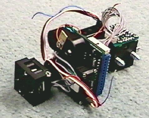

The final module is 10 cm long (4 inches) without the pins and weighs 100 grams (3.5 oz).
The module is absolutely self-contained: it has its own sensors, actuators, cpu,
communication capabilities and power supply.

Manual reconfiguration to snake
mov (17 Mb), mpg
(10 Mb).

Manual reconfiguration to hexapod
mov (17 Mb), mpg
(10 Mb).
The modules can be attached easily to create a modular robot.
In the video we show the procedure to create a snake and a hexapod manually.
One of our goals is to develop the software that allows the robot to
reconfigure from snake to hexapod and back without the user's help.


We built 20 modules so we can build 2 hexapods as those shown in the image.
[home]
[Project Information]
[Related Information]
[1st Prototype]
[2nd Prototype (Hardware)]
[2nd Prototype (Software-Hormones)]
[2nd Prototype (Software-Remote host)]
[68HC12-based board]
Please, let us know of any problems that you find viewing these pages
by mailing to the CONRO Webmaster .
